How to Reduce Thermal Bridging Costs: A Technical Guide to Thermal Breaks
The pursuit of high-performance architecture often hits a thermodynamic wall at the junction of structural necessity and thermal continuity. Thermal bridging—the localized area of a building envelope where a more conductive material allows heat to bypass the insulation layer—remains one of the most persistent challenges in modern construction. How to Reduce Thermal Bridging Costs. While a single steel bolt or an uninsulated concrete slab edge might appear negligible in the context of a 20,000-square-foot building, the cumulative effect of these “thermal leaks” can degrade the total R-value of an assembly by as much as 50%.
Managing these bridges is not merely a matter of adding more insulation. It requires a fundamental shift in how we conceive the building’s structural “skeleton” and its “skin.” As energy codes become more stringent globally, the ability to mitigate these energy drains has moved from the realm of boutique green building into the mandatory requirements of commercial and residential codes. Consequently, the financial implications of thermal bridging are no longer confined to utility bills; they manifest in the sizing of HVAC systems, the longevity of structural components, and the overall capital value of the asset.
To effectively navigate this landscape, one must view the building as a series of thermodynamic intersections. Every balcony, window frame, and masonry tie represents a potential failure point where moisture can condense, leading to mold, rot, and material fatigue. This article serves as a deep technical dive into the strategies, materials, and economic frameworks required to maintain thermal continuity. By treating heat flow as a fluid dynamic that must be meticulously channeled, professionals can protect both the comfort of the occupants and the fiscal health of the project.
Understanding “how to reduce thermal bridging costs”
To grasp how to reduce thermal bridging costs, one must first decouple the idea of “more insulation” from “better performance.” A common misunderstanding in the field is that increasing the thickness of wall batts can compensate for structural bridges. In reality, heat follows the path of least resistance; if a steel stud penetrates that thick insulation, the heat will bypass the fiberglass entirely. The true “cost” of thermal bridging is therefore the inefficiency of the insulation that is there, which effectively becomes a wasted investment.
Oversimplification often leads stakeholders to focus solely on material prices. However, a sophisticated analysis evaluates the “systemic cost.” This includes the labor of installing complex thermal breaks, the potential reduction in HVAC tonnage allowed by a tighter envelope, and the avoidance of long-term remediation costs associated with condensation. When we investigate how to reduce thermal bridging costs, we are actually looking for the “optimization point” where the expense of a thermal break component is offset by the reduction in mechanical system requirements and operational energy spend.
Furthermore, there is a risk in viewing thermal bridging as a purely singular event. Bridges are often compounded. For example, a cantilevered balcony slab creates a massive linear thermal bridge. If the plan ignores this, the interior floor near the balcony remains cold, forcing the HVAC system to work harder to maintain a set point. The cost of this bridge is not just the lost BTU; it is the premature wear on the boiler and the potential loss of tenant satisfaction. A holistic plan prioritizes “thermal decoupling” over “bulk insulation.”
The Evolution of Thermal Continuity in Architecture
Historically, buildings were constructed of high-mass materials like stone or brick, which acted as their own thermal buffers. While these materials are conductive, their sheer thickness provided a form of “thermal lag.” As we moved toward the mid-20th century, the rise of the structural frame—steel and reinforced concrete—changed the thermodynamic profile of buildings. We began filling the gaps between these frames with lighter, non-structural insulation, but the frame itself remained a massive, unmitigated conductor to the outside world.
The late 20th-century energy crises pushed the industry toward the “continuous insulation” (CI) model. This was a revolutionary shift where insulation was moved to the outside of the structural members. While CI significantly reduced the impact of studs, it did not solve the problem of penetrations—balconies, shelf angles, and roof-to-wall junctions. The current era of building science focuses on “point-source” and “linear” bridge mitigation, utilizing high-performance materials like aerogel, fiberglass-reinforced polymers (FRP), and structural thermal breaks (STBs) that can support heavy loads while blocking heat transfer.
Conceptual Frameworks for Heat Flow Mitigation
To manage heat transfer, professionals employ specific mental models that prioritize the “flow” of energy over static values.
1. The “Path of Least Resistance” Model
Imagine heat as water under pressure. If there is a single hole in a dam, the water will find it. In a building, the conductive material (steel, concrete, aluminum) is the hole. The goal is to ensure the “resistive layer” (insulation) is never interrupted by a conductive bypass.
2. The Isotherm Analysis Framework
This involves visualizing the temperature gradient through a wall. In a bridge-free assembly, the isotherms (lines of equal temperature) are straight and parallel to the wall. At a thermal bridge, these lines “bunch up” and pull the cold temperature deep into the interior. The framework seeks to keep the interior surface temperature above the “dew point” at all costs.
3. The Structural-Thermal Decoupling Model
This mental model separates the building into two distinct systems: the internal structure that holds the weight and the external “skin” that manages the environment. Any connection between the two must be made through a “thermal gatekeeper”—a material that provides structural strength but has low thermal conductivity.
Categories of Thermal Breaks and Structural Interventions
There is no “one-size-fits-all” solution. The strategy depends on the structural load and the specific geometry of the bridge.
1. Linear Thermal Breaks (Balconies and Slabs)
Usually comprised of an insulating block (like EPS or Rockwool) sandwiched between stainless steel rebar. These are cast into the concrete to separate the interior slab from the exterior projection.
-
Trade-off: High initial cost but eliminates the most significant source of heat loss in multi-family housing.
2. Point Thermal Breaks (Fasteners and Ties)
Using non-conductive materials like basalt-fiber or fiberglass for masonry ties and cladding attachments.
-
Trade-off: Minimal structural impact, but requires specialized engineering to ensure wind-load and seismic requirements are met.
3. Thermal Break Pads (Steel-to-Steel)
High-density, reinforced polymer plates placed between steel connections (e.g., where a canopy beam meets a column).
-
Trade-offs: Effectively “breaks” the bridge, but can affect the “stiffness” of the connection, requiring larger bolts or thicker plates.
Comparison of Thermal Mitigation Strategies
| Strategy | Conductivity Reduction | Structural Load Capacity | Cost Factor | Ease of Install |
| Mineral Wool CI | High | Low | Medium | High |
| FRP Structural Breaks | Very High | High | High | Moderate |
| Aerogel Shims | Extreme | Moderate | Very High | Low |
| Stainless Steel Ties | Moderate | High | Medium | High |
Real-World Scenarios: From High-Rises to Residential Units How to Reduce Thermal Bridging Costs
Scenario A: The Modernist Glass High-Rise
In a building with floor-to-ceiling glass, the slab edges are often exposed. Without mitigation, these edges act like “cooling fins.”
-
The Plan: Implementation of a “thermal slab edge” break and the use of thermally broken window frames.
-
The Second-Order Effect: By reducing the cold draft at the floor, the building can eliminate the need for expensive perimeter baseboard heating, significantly reducing mechanical costs.
Scenario B: The Masonry-Clad Hospital
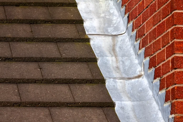
Hospitals require high indoor air quality and precise temperature control. Masonry shelf angles—steel brackets that hold the brick—can create hundreds of linear feet of thermal bridging.
-
The Plan: Utilize stand-off shelf angles that use point-attachments rather than a continuous steel plate.
-
Risk Avoidance: Prevents condensation behind the brick, which is a common source of mold in healthcare environments.
Economic Dynamics: Lifecycle vs. Upfront Capital
The financial modeling for thermal bridges must account for the “negative space” of energy savings. When evaluating how to reduce thermal bridging costs, the developer must calculate the “Internal Rate of Return” (IRR) of the thermal break.
Range-Based Table: Cost-Benefit Analysis (Per Unit/System)
| Component | Upfront Premium | HVAC Sizing Reduction | Energy Savings (Annual) | Payback Period |
| Balcony Breaks | $1,500 – $3,000 | 5% – 8% | $150 – $300 | 7–12 Years |
| FRP Masonry Ties | $500 – $1,200 | 2% – 4% | $40 – $80 | 8–15 Years |
| Thermal Stud Shims | $0.50 – $1.50/ft | 1% – 2% | $10 – $20 | 3–5 Years |
Strategic Tools and Support Systems
Managing thermal bridges in the 21st century is a digital-first endeavor:
-
2D and 3D Heat Flow Modeling (THERM/BISCO): Allows engineers to see exactly where heat is escaping before the first brick is laid.
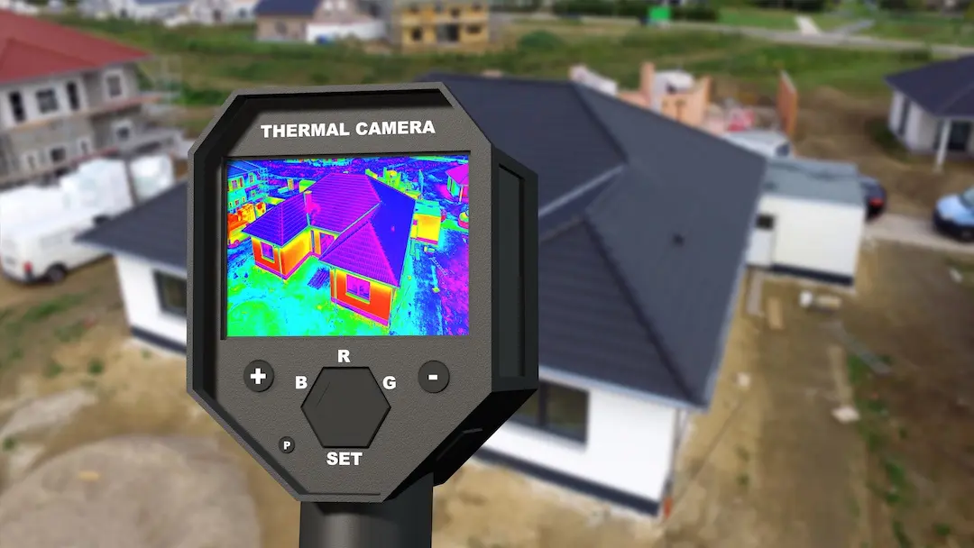
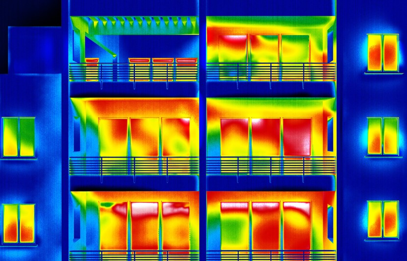
-
Infrared Thermography: Used post-construction to verify that thermal breaks were installed correctly and that no “anomalous” bridges exist.
-
Psychrometric Charts: Essential for determining the “dew point” and ensuring the internal surface temperature of a bridge won’t trigger condensation.
-
Life Cycle Assessment (LCA) Software: Tracks the carbon footprint of the thermal break material versus the energy it saves over 50 years.
Risk Landscape: Condensation and Structural Integrity
The greatest risk of a thermal bridge is not the energy bill; it is the “dew point” crossover. When warm, humid interior air hits a cold spot (the bridge), it turns into liquid water.
-
Taxonomy of Failure:
-
Interstitial Condensation: Water forming inside the wall, rotting the studs.
-
Surface Mold: Often found in the upper corners of rooms where the roof-to-wall junction is poorly insulated.
-
Frost Wedging: In cold climates, water trapped in a bridge can freeze and expand, eventually cracking masonry or concrete.
-
Maintenance, Governance, and Long-Term Adaptation
A building’s thermal envelope is a “living” system that degrades over time.
-
Review Cycles: Every 10 years, an infrared audit should be conducted to ensure that settling or moisture haven’t compromised the insulation or the thermal breaks.
-
Governance: The “Building Manual” must clearly label the location of structural thermal breaks. Future renovations (like adding a new sign or awning) must be prohibited from “piercing” the thermal envelope without a new mitigation strategy.
Evaluation Metrics: Tracking Thermal Performance
-
The U-Value (Thermal Transmittance): The goal is a low overall U-value for the entire assembly, including the bridges.
-
The Chi-Factor ($\chi$): A measure of the heat loss through a point thermal bridge (W/K).
-
The Psi-Value ($\psi$): A measure of the heat loss through a linear thermal bridge (W/mK).
-
Documentation Example: “Junction A-12 (Slab Edge): $\psi$-value 0.05 W/mK. Target < 0.10. Performance verified via THERM 7.8.”
Common Misconceptions and Oversimplifications
-
Myth: “Wood doesn’t have thermal bridges.” Correction: While less conductive than steel, wood studs still bridge the insulation, often reducing a wall’s effective R-value by 20%–30%.
-
Myth: “Thermal breaks weaken the building.” Correction: Modern structural thermal breaks are engineered to handle the same shear and moment loads as solid concrete or steel.
-
Myth: “If I use triple-pane windows, I don’t need to worry about the frame.” Correction: The frame is the bridge. High-performance glass in a standard aluminum frame is a wasted investment.
The Synthesis of Structure and Thermodynamics
The ultimate goal in understanding how to reduce thermal bridging costs is to achieve “thermal symmetry.” A building that is thermally symmetrical has no cold spots, no drafts, and no hidden moisture traps. This is the hallmark of a truly “permanent” structure. By investing in the invisible junctions—the pads, the clips, and the breaks—the architect ensures that the building’s efficiency is “baked in” to the structure itself, rather than added on as an afterthought. As the global economy moves toward carbon neutrality, the mitigation of thermal bridging will stand as the most significant leverage point in building design, transforming the envelope from a simple enclosure into a masterwork of thermodynamic control.