How to Avoid Poor Flashing Risks: The Architect’s Guide to Moistur
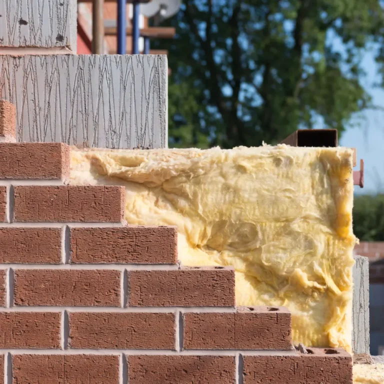
The integrity of a building envelope is rarely compromised by the failure of its primary surfaces; rather, the vulnerability lies at the transitions. In the discipline of architectural moisture management, flashing serves as the critical connective tissue between disparate materials—windows to masonry, roof planes to chimneys, and cladding to foundations. How to Avoid Poor Flashing Risks. While a facade may cover thousands of square feet, the few linear inches of flashing at a sill or a head determine whether the structure remains a dry sanctuary or becomes a liability of rot and mold. The complexity of these systems is often obscured by their small scale, leading to a dangerous undervaluation of their engineering during the planning phase.
A sophisticated approach to building longevity recognizes that water is an opportunistic force, driven by gravity, capillary action, and air pressure differentials. Flashing is the mechanical response to these forces, designed to redirect water away from the structural core and back to the exterior. However, as contemporary architecture pushes toward complex geometries and “clutter-free” minimalist aesthetics, the traditional methods of flashing are being challenged. Achieving a high-performance seal in modern construction requires a synthesis of material science and geometric logic that many standard building practices fail to provide.
This analysis moves beyond the cursory “best practices” often found in trade manuals. Instead, it examines the systemic nature of moisture intrusion and the strategic foresight required to ensure that transitions remain impervious over a fifty-year lifespan. By dissecting the chemical compatibility of membranes, the physics of kick-out angles, and the economic fallout of installation oversights, we provide a definitive framework for navigating the most volatile aspect of the building envelope.
Understanding “how to avoid poor flashing risks”
In the professional architectural lexicon, the objective of how to avoid poor flashing risks is not merely about preventing a visible drip; it is about managing the microscopic movement of vapor and liquid at the building’s most stressed junctions. One of the primary misunderstandings among developers and contractors is the belief that high-quality flashing can be “applied” as a secondary thought. This perspective fails because flashing is a systemic component, not a surface treatment. If the sequencing of the building wrap, the window flange, and the head flashing is incorrect, even the most expensive copper or liquid-applied membrane will serve as a funnel for water rather than a shield.
Oversimplification in this domain often manifests as an over-reliance on sealants—caulking—as a substitute for mechanical flashing. A “premium” plan recognizes that sealants are temporary and prone to UV degradation, whereas mechanical flashing is a permanent architectural geometry. Understanding how to mitigate these risks requires a multi-perspective analysis: the installer must view it as a puzzle of overlapping layers (shingle-fashion), the architect must view it as a thermal and moisture boundary, and the owner must view it as a long-term insurance policy against structural rot.
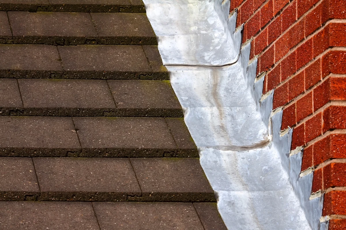
A critical risk often overlooked is “galvanic incompatibility.” When different metals—such as aluminum flashing and pressure-treated lumber—interact in the presence of moisture, a chemical reaction occurs that can eat through the flashing in a matter of months. Therefore, avoiding risk is as much about chemistry as it is about geometry. A comprehensive strategy must account for the chemical marriage of the metals, the adhesives, and the substrate to ensure that the transition doesn’t become a site of hidden corrosion.
Deep Contextual Background: Historical Evolution
The history of flashing is a transition from organic bulk to engineered precision. In vernacular architecture, water management was achieved through massive overhangs and sacrificial materials. Thatch roofs and thick stone walls relied on depth to prevent water from reaching the interior. As building envelopes became thinner and more lightweight in the 20th century, the burden of moisture protection shifted to specialized materials.
Early 20th-century flashing primarily utilized lead and copper. These materials were favored for their malleability and longevity, allowing craftsmen to “work” the metal into complex shapes at chimney saddles and valleys. However, the post-war housing boom demanded faster, cheaper solutions, leading to the rise of aluminum and galvanized steel. While effective, these materials lacked the longevity of copper and were prone to the aforementioned galvanic corrosion.
The modern era was defined by the introduction of “peel-and-stick” membranes and liquid-applied flashings. These synthetic solutions allowed for a continuous air and water barrier, bridging the gap between traditional metal flashing and modern building wraps. We are now in a phase where “hybrid” systems—combining the rigidity of metal with the seamlessness of high-performance tapes—are the standard for high-performance envelopes. This evolution has moved the trade from one of “bending metal” to one of “managing chemistry.“
Conceptual Frameworks and Mental Models
To evaluate flashing systems, professionals should utilize these mental models to ensure no technical gap exists.
1. The “Shingle-Fashion” Logic
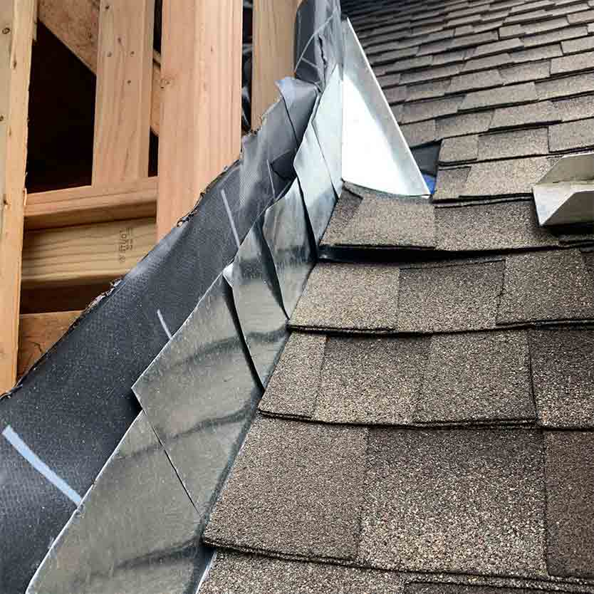
The most fundamental rule of flashing is that every upper layer must overlap the lower layer. Gravity is the primary driver of water; if a lower membrane is tucked over an upper one, water will inevitably find its way behind the system. This model is the first line of defense against the “sequencing error” failure mode.
2. The Capillary Break Framework
Water can move upward through tight spaces through capillary action. This framework dictates that flashing must include “drip edges” or physical gaps that break the surface tension of water, forcing it to fall away from the building rather than “wicking” into the assembly.
3. The Pressure-Equalized Rain-screen
This model treats the cladding as a “filter” and the flashing as the “drain.” It assumes that some water will get behind the siding. Therefore, the flashing must not only prevent water from entering but also provide a path for the air to circulate and dry any incidental moisture. If flashing is too tight, it can trap moisture and accelerate rot.
Key Categories and Variations
Selecting a flashing strategy involves weighing the material life-span against the complexity of the installation.
| Category | Material | Primary Advantage | Trade-off |
| Rigid Metal | Copper / Stainless Steel | 50+ year lifespan; highly durable | High cost; requires skilled soldering |
| Flexible Membrane | Butyl / Acrylic Tapes | Self-sealing around fasteners | UV sensitivity; 15-20 year lifespan |
| Liquid-Applied | Silyl-Terminated Polyether | Seamless; handles complex curves | Requires specific temperature for curing |
| Vinyl / PVC | High-density plastic | Corrosion-proof; inexpensive | Brittle in cold; high thermal expansion |
| Lead-Free Composite | Aluminum mesh + polymer | Malleable like lead; safe | High cost per linear foot |
Decision Logic: Material Match
The logic of selection is driven by the “Accessibility Variable.” If the flashing is buried behind a masonry veneer that is intended to last 100 years, the logic dictates a rigid metal system (Copper or Stainless). If the flashing is easily accessible for maintenance, a high-performance flexible membrane may be the more cost-effective choice.
Detailed Real-World Scenarios How to Avoid Poor Flashing Risks
Scenario A: The Window Head in a High-Wind Coastal Zone
In coastal environments, wind-driven rain can push water horizontally and even vertically up a facade.
-
Constraint: 120 mph wind gusts.
-
Failure Mode: Relying on a standard “L-flashing” without an end-dam. Water is blown off the ends of the flashing and into the wall cavity.
-
Solution: Specify “end-dams”—small upturned edges at the ends of the head flashing—to contain the water and force it forward.
Scenario B: The Deck-to-Wall Transition
One of the most common sites of structural collapse in residential construction.
-
Constraint: Constant movement from foot traffic and wood shrinkage.
-
Risk: “Z-flashing” that is not integrated with the house wrap. Water leeches into the rim joist.
-
Second-Order Effect: Hidden structural rot that goes unnoticed until the deck becomes detached from the house.
Planning, Cost, and Resource Dynamics
The economic reality of flashing is that it represents less than 1% of the total build cost but accounts for over 70% of construction defect litigation.
Range-Based Resource Allocation (per Linear Foot)
| Component | Basic Cost (USD) | Premium Cost (USD) | Impact of “Premium” Choice |
| Flashing Material | $0.80 – $1.50 | $5.00 – $12.00 | Extends lifespan by 40+ years |
| Sealing Tapes | $0.50 – $1.20 | $2.50 – $4.00 | Better adhesion in extreme temps |
| Specialist Labor | $2.00 – $4.00 | $8.00 – $15.00 | Reduces “sequencing” errors |
Opportunity Cost: By saving $2,000 on cheaper flashing materials during a $500,000 build, a developer risks a $100,000 mold remediation and structural repair project within the first decade. This is an irrational economic trade-off.
Tools, Strategies, and Support Systems
Successful flashing execution relies on a specialized set of technical strategies:
-
Metal Brakes: Precision machinery used to create crisp, consistent angles in metal flashing on-site.
-
J-Rollers: Essential for ensuring full pressure-sensitive adhesion of flexible membranes.
-
Back-Dam Strips: Pre-manufactured profiles that ensure window sills tilt outward.
-
Compatibility Matrices: Charts provided by manufacturers to verify that “Tape A” won’t dissolve “Wrap B.“
-
BIM Detail Libraries: Digital repositories of “standardized” flashing details to ensure consistency across large crews.
-
Ultrasonic Thickness Gauges: Used on-site to verify that liquid-applied flashing meets the required “mils” (thickness).
Risk Landscape and Failure Modes
The taxonomy of flashing risk is defined by “invisible” vulnerabilities.
-
The “Reverse-Lap” Error: An upper layer of building wrap is tucked into the flashing rather than over it.
-
The “Short-Leg” Problem: The vertical leg of the flashing is too short (less than 4 inches), allowing wind-driven rain to blow up and over the top.
-
Chemical Incompatibility: Using a rubberized-asphalt tape on a flexible PVC window flange, which can lead to “plasticizer migration,” causing the tape to turn into a gooey, non-sealing mess.
Governance, Maintenance, and Long-Term Adaptation
Flashing is a “set and forget” component in theory, but in practice, it requires long-term governance.
Maintenance Checklist:
-
Pre-Winter Audit: Inspect all kick-out flashing for debris. A single leaf can redirect an entire roof’s worth of water into a wall.
-
5-Year Caulk Review: While caulk is secondary, it protects the “edges” of the flashing. Replace any cracked or brittle sealant.
-
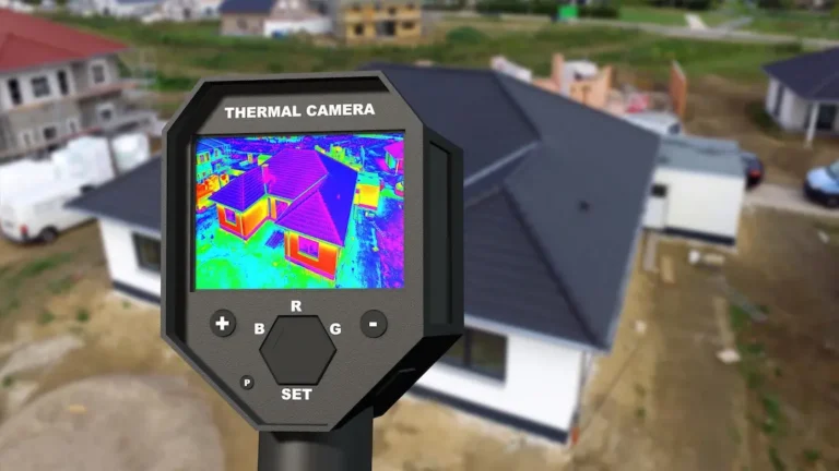
Infrared Drone Scans: On commercial buildings, annual thermal scans can identify “cool spots” in the wall that suggest moisture is bypassing the flashing.
Measurement, Tracking, and Evaluation
Quantifying the success of how to avoid poor flashing risks involves both leading and lagging indicators.
Leading Indicators:
-
Sequencing Audit: A checklist signed off by a supervisor before the siding is installed.
-
Adhesion Pull-Tests: Verifying that tapes have achieved a permanent bond to the substrate.
Lagging Indicators:
-
Warranty Claims: Tracking the frequency of window-leak calls.
-
Moisture Probe Data: For high-end estates, embedding moisture sensors in the “splash zones” of critical transitions.
Common Misconceptions and Oversimplifications
-
“Caulk is a type of flashing.” Caulk is a sealant; flashing is a mechanical redirector. Never rely on caulk to do the work of a metal edge.
-
“Tape is just tape.” Many cheap tapes lose their “tack” at freezing temperatures; specify all-weather acrylics for serious projects.
-
“Window manufacturers handle the flashing.” Manufacturers provide the window; the interface between the window and the house is the responsibility of the installer and the plan.
-
“Copper lasts forever.” Copper is exceptionally durable, but it will corrode if it comes into contact with runoff from a cedar roof (which is acidic).
-
“If it doesn’t leak now, it’s fine.” Flashing failures are often “slow-motion” disasters, taking 5-7 years for rot to become visible.
Ethical and Practical Considerations
There is an ethical dimension to flashing in the context of “Climate Resilience.” As storms become more frequent and intense, the historical “minimum code” for flashing is no longer sufficient. Specifiers have a responsibility to design for “worst-case” scenarios, especially in affordable housing where residents may lack the resources to fund massive repairs later. Investing in premium flashing is an act of “durable sustainability”—preventing the premature demolition and landfilling of structural components.
Conclusion: Synthesis and Judgment
The mastery of building transitions is the hallmark of professional architecture. While the facade represents the building’s face, the flashing represents its conscience—the hidden, unglamorous work that ensures the structure remains true to its purpose. Avoiding risk is not about complex technology; it is about the disciplined application of simple physics: gravity, chemistry, and geometry.
By treating flashing as a primary structural system rather than a finishing detail, stakeholders can insulate themselves from the most common and costly cause of building failure. The transition from a “standard” build to a “legacy” build is found in those few inches of overlapping metal and membrane. Intellectual honesty in construction requires us to admit that we cannot stop water; we can only hope to out-negotiate it through superior planning and meticulous execution.